Version: 2.3
Back to:
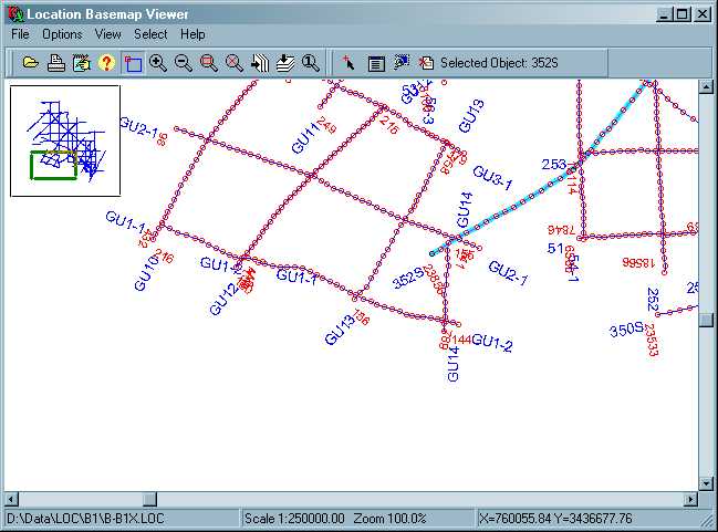
BASEVIEW is primarily intended for viewing "location data", or base maps, used to locate objects in Lynx Exploration Adviser and Exploration Archivist projects. It uses the LEA Object and LEA Map Object. BASEVIEW can alos be used to view point, line and polygon data. This version of BASEVIEW supports both "UKOOA" format and ESRI Shape files.
A locations file can be opened for viewing in three ways:
- Select the File-Open menu option, and select the file in the open file dialogue
- Specify the file on the command line when starting BASEVIEW
- Drag the file from an explorer window, and drop it on BASEVIEW
BASEVIEW can conveniently be started by double clicking its icon in Launcher, or from a command line or script.
BASEVIEW can be run with a command line similar to the following:
BASEVIEW [LOCFILE]
where:
LOCFILE is an optional location data file or shape file. If no LOCFILE is specified, you can select one from the dialogue box which appears when you click the File-Open menu or tool bar button.
BASEVIEW parameters control the display and annotation of location maps. Editing is via the standard LEA parameter editor PRMEDIT. Parameters are saved in files with a .bvw extension.
User-default parameters are read from the file DEFAULT.BVW in your LEA user-custom directory.
BASEVIEW parameters are displayed in the following pages:
Display Margin (px)
The size of the margin around the edge of the displayBackground Colour
Select a colour for the background colour for the displayShow Grid
YES/NO: turns on or off a background grid of the coordinates (not implemented)Horizontal Interval
For the coordinate grid, sets the interval between grid lines in the X (longitude) direction (not implemented)Vertical Interval
For the coordinate grid, sets the interval between grid lines in the Y (latitude) direction (not implemented)Grid Colour
Select the colour in which the coordinate grid will be drawn (not implemented).Show Overview
YES/NO - toggle display of the overview windowShow Scalebars
YES/NO - toggle display of the map coordinate scalebars along the top and left of the window.Coordinate Display
XY/Lat-Lon - for location files which contain both projected (XY) and unprojected (Lat-Lon) coordinates, you can choose which coordinate system to display. For location files which only contain one coordinate system this option is disabled.
Annotation for Line objects (seismic lines or other linear features)
Line Style
Select from: Solid, Dash, Dot, Dash-Dot, Dash-Dot-Dot, None, Dithered
Sets the type of line used to join the line nodes (such as seismic shotpoints) on the map.
For any option other than SOLID, the Line Width (below) must be set to 1Line Colour
Select the colour of the line used to join the line nodes.
Line Width (px)
Sets the thickness (in pixels) of the line used to join the line nodes.Show Line Labels
YES/NO - toggle display of a label for each line
Select from:Label Placement
Select where line labels will appear.
Choose from:
- START - labels will appear before the start of the line
- END - labels will appear after the end of the line
- BOTH - labels will appear both before and after the line (default)
Label Colour
Select the colour of the line labelsLabel Size (points)
Set the size of the labels in font pointsLabel Orientation
Set the orientation for the line labels
Choose from
- HORIZONTAL - display the labels horizontally across the screen
- VERTICAL - display the labels vertically down the screen
- PARALLEL - display the labels parallel to the line direction (default)
- PERPENDICULAR - display the labels at right angles to the line direction
Note: some fonts may fail to display in vertical, parallel or perpendicular orientations at certain sizes
Symbol Type
The symbol used to display each line node/shotpoint. Choose from:
- NONE - nodes are not displayed. Note that you can use this option to display stick maps, since the lines joining nodes will still be displayed.
- DOT
- CUSTOM (not implemented)
- CROSS
- PLUS
- CIRCLE
Symbol Colour
Select the colour of the node/shotpoint symbolSymbol Size (px)
The size in pixels of the node/shotpoint symbolSymbol Placement
Determine the interval for display of nodes. Choose from:
- ALL - all nodes will be displayed (default)
- ENDS - the first and last nodes will be displayed
- INCREMENT - every nth node will be displayed. Set the interval below.
Symbol Interval
Set the interval used for node/shotpoint display when Symbol Placement (above) is INCREMENTShow Node Labels
YES/NO - toggle display of node labelsLabel Placement
Determine the interval for display of node labels. Choose from:
- ALL - all node labels will be displayed
- ENDS - labels for the first and last nodes will be displayed (default)
- INCREMENT - a label will be displayed for every nth node. Set the interval below.
Label Interval
Set the interval used for node/shotpoint label display when Label Placement (above) is INCREMENT.Label Colour
Select the node label colour.Label Size (points)
Set the size of the node labels in font points.Label Orientation
Select how the node labels are displayed with respect to the line:
- HORIZONTAL - node labels are always horizontal
- VERTICAL - node labels are always vertical
- PARALLEL - node labels will be displayed parallel to the line direction
- PERPENDICULAR - node labels will be displayed at right angles to the line direction (default)
Decimal Places
Select the number of decimal places to use in the display of numeric node labels (ie shotpoint numbers).
This parameter page sets the display options for objects defined as points in active layers.
Symbol Type
Determines how objects defined as points are displayed.
Choose from:
- NONE - points are not displayed
- DOT
- CUSTOM (not implemented)
- CROSS
- PLUS
- CIRCLE
Symbol Colour
Select thecolour in which the symbol defined above will be drawn.
Symbol Size (px)
The size of the symbol defined above, in pixels.
Show Point Labels
YES/NO - toggle display of a label for each point.Label Placement
Set where labels are positioned relative to the point: LEFT, RIGHT, ABOVE, BELOWLabel Colour
Select the colour in which the point label will be drawn.
Label Size (points)
The size in which the point label will be drawn (in font points)
Line Style
Select from Solid, Dash, Dot, Dash-Dot, Dash-Dot-Dot, None, Dithered
The type of line used to draw each polygon.
For any option other than SOLID, the Line thickness (below) must be set to 1Line Colour
Select the colour of the line used to draw each polygonLine Width (px)
The thickness in pixels of the line used to draw each polygonShow Polygon Labels
YES/NO - toggle display of a label for each polygon. Labels will be drawn in the centre of each polygon.Label Colour
Select the colour in which to draw the labelLabel Size (points)
The size (in font points) in which to draw the label.
Changes you make here will be saved as your user-default display properties for BASEVIEW, and used each time BASEVIEW is opened. You can discard all your changes and reset to the system default display properties using the Options-Revert to Defaults menu option.
Switch display coordinate system to display file?
The
file you are attempting to open contains a different coordinate system to the current display
parameters. Standard "UKOOA"-type locations files usually contain both projected and unprojected
coordinates, so you can switch between the two coordinate systems within BASEVIEW (see
General Parameters - Coordinate Display). However, some locations files
(and all shape files) only contain a single coordinate system. This message warns you that the
display coordinate system is being changed in order to display the current file.
See also:
[ LEA Parameter Editor]
[The LEA Object]
[The LEA Map Object]
[Viewer Common Functionality]
[Viewers
Index]
[Main Index]