
1. Introduction
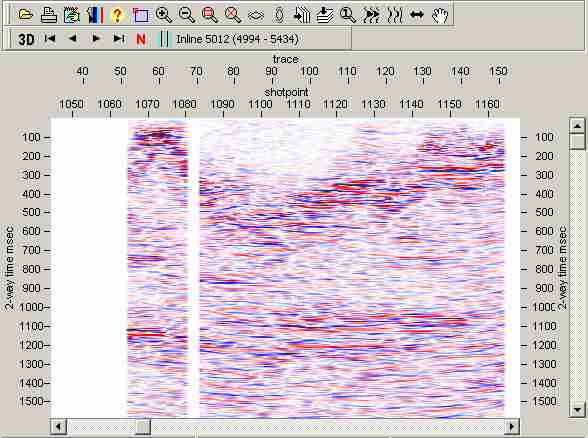
The SEIS3D toolbar in Seisview and Seismap allows 3D seismic files to be viewed by inline or crossline. You can view each inline sequentially, or select the inline to view by number.
SEIS3D is incorporated into SeisView and Seismap as a toolbar, but is separately licensed. If the 3D toolbar and the 3D menu in Seisview and Seismap are not enabled, then SEIS3D is not licensed, and you need to activate it by contacting Lynx to acquire a licence.
2. Menu and Toolbar Options
- 3D - main menu option
- Edit 3D Options

(SeisView only)
Displays a PRMEDIT window to edit the display parameters. See Parameters below for details. - First Inline

View the first inline in the seismic 3D volume. Inlines will always be sorted into ascending numeric order. - Previous Inline

View the previous inline in the seismic 3D volume. - Next Inline

View the next inline in the seismic 3D volume. - Last Inline

View the last inline in the seismic 3D volume. - Show Inline Number

Enter the number of the inline to display. - Interpolate Missing Traces

Turn on/off the lateral interpolation of missing traces in the 3D volume.
- Edit 3D Options
3. Parameters
SEIS3D 3D display parameters are saved as a page in the SEISVIEW display parameters file.
3.1 3D Seismic Options
View as 3D inlines - YES/NO
NO (default) - all traces from the seismic file are displayed as a 2D profile
YES - select the header slots for the inline and crossline numbers below.
Each inline will be displayed as a separate profile. You can use the
toolbar options (above) to view the 3D volume.
SEG-Y Format - Standard/Revision-1
Standard (default) - use the header slots below to specify the trace header slots from which
inline and crossline numbers will be read.
Revision-1 - use the trace header slots defined in the SEG-Y Revision-1 format specification to read inline
and xline numbers automatically.
Inline header bytes
Xline header bytes
Select the trace header slots from which the inline and crossline numbers will
be read for Standard SEG-Y. For Standard SEG-Y data these are often bytes 9-12 for the inline,
and 17-20 for the crossline, but there is no accepted default. SEG-Y Revision 1 suggests
using bytes 189-192 for the inline and 193-196 for the crossline.
SEG-Y 3D files are usually arranged with each inline stored
sequentially, and crosslines increasing sequentially within each inline. SEIS3D indexes the
inline and crossline number of each trace, allowing you to view a 3D volume by either inline- or
crossline-profile. To view a 3D volume by crossline-profile, simply switch the inline and crossline
header slots.
Number format
INT-4 - header values will be read as
4-byte little endian (Intel-format) integers.
INT-4 (REV) (default) - header values will be read
as 4-byte big-endian (Motorola/Network-format) integer. This is the default format for SEG-Y.
Pad inlines at ends
NO (default) - inlines will be displayed with differing lengths. Gaps within the crossline sequence
for each inline will always be padded, but blank traces will not be added to the start and end of each
inline to make all inlines the same length.
YES - all inlines will be padded with blank traces at the start and end to the maximum crossline extent
for the 3D volume as a whole.
4. Error Messages
Listed below are the error messages that may be generated by SEIS3D.
If an error occurs, the display format will be set back to 2D.
File format not supported - not all seismic file formats which can be viewed as 2D profiles in SEISVIEW can be viewed as 3D data. At present SEG-Y and Lynx TR-files are supported by SEIS3D.
Repeated XLine - a duplicate crossline has been found for the specified inline. This suggests that you have selected the wrong header slot for the crossline number.
Maximum XLines exceeded - the crossline range within the 3D volume is too great, and creating a trace index of this size for each inline may run into memory allocation problems. The maximum crossline range can be modified by editing the max padded inlines key in the [startup] section of SEIS3D.INI. This value is checked when you have selected to pad inlines to the maximum crossline extent for the 3D volume. It suggests that either you have a very large 3D volume, or you have selected the wrong header slot for the crossline numbers.