
1. Introduction
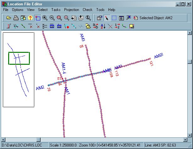
LOCPREP is an interactive editor for Lynx and UKOOA type location files, which store seismic shotpoint location information, and can also store general location information. You can use LOCPREP to perform a variety of tasks with LOC files, including renaming lines, editing or deleting or renumbering shotpoints and joining and splitting lines.
2. Running LOCPREP
If no LOC file is specified on the command-line, open a LOC file
using the File-Open menu, or by dragging a LOC file onto the LOCPREP window
from an Explorer window.
You can change the display and annotation options for the location
file using the Options-Edit Parameters menu.
The Tasks menu lists the editing
options available within LOCPREP for manipulating the LOC file. Some options require a
seismic line, or multiple seismic lines, to be selected before the option is available. To select
lines from a list, use the Select-Select Object From List menu option which displays a list
of the seismic lines in the current LOC file - this list can be sorted by clicking on the header
row of the list. To select lines on the map, use the Select-Select Object menu option -
select a single line by clicking near it, and select multiple lines by holding down the
<CTRL> key while selecting the second and subsequent lines.
When you have completed
editing, use the File-Save As menu to save your LOC file.
2.1 Command-line options
LOCPREP can be started with a command-line similar to the following:
LOCPREP [-cPROJFILE] [LOCFILE]
where:
PROJFILE is the full path of an optional projection configuration file with a LPJ extension, used for map projection conversions. This file can be created using the Projection-Save Projection File menu.
LOCFILE is the full path of a LOC file to open on program startup.
3. Menus and Controls
3.1 Main Menu
- File
- Open

Select an input LOC file via the standard Open dialogue. The selected file will be copied to your USER SCRATCH folder (usually c:\Users\
\AppData\LynxData\scratch ) and all modifications will be applied to this file rather than directly to the input file. Use the Save As option (below) to save changes to your LOC file. Note that the temporary files in the scratch folder will not be deleted automatically when LOCPREP exits, so it is recommended that you occasionally clear this folder manually. - Print

Print a screen snapshot or the full image. for more details see Viewer Common Functionality - Print
- File Attributes
Displays LEA Map Object attributes for the currently open file (if the LEA Map Object is installed and registered).
- Save As
Select a new file name for the output file, or overwrite the input file using the standard Save dialogue.
The "Save as type" drop down list in the Save dialog box has options for controlling the format of the output loc file. You can save the file as a standard Lynx LOC file, or
"Loc file don't add metadata" saves the LOC file without including the metadata generated during the current session, i.e. since the input file was opened.
"Loc file with lct catalogue" saves the LOC file with an additional index file used by Lynx's (now obsolete) CDVU application.
"LFCR delimited text" saves the loc file as 80 byte records, separated by line feed and carriage return formatting characters (0A and 0D hexadecimal). - Import
- Import from Text File
Launch LOCCONV to create a new temporary LOC file from a selected text file containing line shotpoints and coordinates. When LOCCONV closes, the new LOC file will be displayed in LOCPREP and can be saved using the File-Save As menu.
- Import From Shape File
Create a new temporary LOC file from a selected shape file. Enter or browse for the shape file name, and select the field number from its attribute table to use as the line name.
The following shape-types are supported:
Point, PointM, Polyline, PolyLineM, Polygon, PolygonM, Multipoint, MultipointM.
For polyline and polygon types, each input line-part will be stored as a separate object in the output LOC file.
If M values are present in the input shapefile, these will be stored as the 'shotpoint' values in the output LOC file, otherwise, the shotpoint values will be sequential.
After import, the new temporary LOC file will be displayed in LOCPREP and can be saved using the File-Save As menu.
- Import from Text File
- Export
-
Export to Text File
Create a new character-delimited ASCII Text (CSV) file from the current LOC file.
If a LOC file is currently loaded, its file path will be displayed in the Input LOC file parameter. If a LOC file is not currently loaded, you can enter the name of a LOC file here.
The output file is suitable for use in Microsoft Excel, and for import into databases.
Select the coordinates to output - either latitude/longitude or XY coordinates. Only one coordinate system will be written to the output file.
Specify the delimiter for the output CSV file. The default value is a comma. However, if your decimal separator is a comma, you should change the delimiter to some other character such as a semi-colon (;).
Enter or browse for the output CSV file name. If the output file already exists, it will be overwritten. -
Export to Shape File
Create a new shape file from the current LOC file.
If a LOC file is currently loaded, its file path will be displayed in the Input LOC file parameter. If a LOC file is not currently loaded, you can enter the name of a LOC file here.
Select the coordinates to output - either latitude/longitude or XY coordinates. Shape files can only contain one coordinate system.
Select the shape type to output - supported types are: Point, PointM, Polyline, PolyLineM, Polygon, PolygonM, Multipoint, MultipointM. If the output shape type has M-values, the shotpoint value will be used, otherwise, shotpoint values will be dropped.
You can also select fields to include in the attribute table: linename, first and last shotpoints and line length in km. Either use the default field names for these attributes, or enter your own fieldnames, which must be valid dBASE fieldnames - ie maximum 10 characters, comprising only uppercase letters A-Z, digits 0-9 and underscores.
For output points, each record of of each input object will be output as a separate point object.
For output polygons, the first point will be duplicated and shotpoints re-ordered if necessary to create a closed clockwise loop, however, this may create invalid polygons if the polygon perimeter intersects itself
Enter or browse for the output shapefile name. If the output file already exists, it will be overwritten.
The attribute table (DBF)for the output shape file will also be created. -
Export to PICS Cultural File
Create a new PICS cultural metadata file from the current LOC file. This file can be imported into WinPICS as cultural data (or converted into PICS cultural data using the command-line utility LMKMETA).
If a LOC file is currently loaded, its file path will be displayed in the Input LOC file parameter. If a LOC file is not currently loaded, you can enter the name of a LOC file here.
Select the colour to use for the cultural data, and enter or browse for the output file name. If the output file already exists, it will be overwritten.
-
Export to Text File
- Open
- Options
- Edit Parameters

Displays a PRMEDIT window to edit the display parameters. See BaseView Parameters for details.
The display parameters used in LOCPREP are the same as the display parameters used by BASEVIEW, but each program has an independent user-default parameter file.Changes you make here will be saved as your user-default display properties for LOCPREP, and used each time LOCPREP is opened. You can discard all your changes and reset to the system default display properties using the Options-Revert to Defaults menu option.
- Set Scale
Set the base scale for display of the location data as a ratio (eg 1:250000). You can zoom in and out from this base scale using the options in the View menu, but this scale will be used to print the map.
- Revert to Defaults
Remove all user customisations and return to the system-defined display options. Any modifications you have made to the display and annotation parameters will be lost.
- Edit Parameters
- View
The standard view manipulation functions on this menu are described in Viewer Common Functionality - Main Toolbar
- Select
The standard selection tools on this menu are described in Viewer Common Functionality - Selection Toolbar
- Tasks
- Auto-Split Profiles

This option works on all profiles in the LOC file.
Use it to split a profile into one or more parts when the distance between successive location points exceeds the threshold you specify. This option can be used to split profiles which have the same name but which should not really be connected. At each location point "jump", succeeding location points are assigned a modified profile name. This is made up of the initial profile name, plus a "suffix character" and a numeric sequence number. For example, suppose the profile AX-50 is split into three parts, with a suffix character of *, the new profiles will be calledAX-50
AX-50*1
AX-50*2
- Create New Profile from Intersections

See Create New Profile from Intersections below
- Decimate Shotpoints

This option works on selected lines or all lines in the LOC file.
This enables the size of the input file to be reduced, by cutting out some of the shotpoint records in each profile.- All Lines - perform decimation on all lines in input file
- Selected Lines - perform decimation on currently selected lines.
- Factor - every nth input record is output
- Shotpoint - records are output if the shotpoint is a multiple of the interval entered. For example, if you enter an interval of 20.0, shotpoints 20, 40, 60 etc. will be selected. Note that for this to work, the input file must actually contain shotpoints at multiples of the interval - LOCPREP will not do any interpolation.
- Distance - the distance between sucessive records is calculated, and records are output if the distance is greater than the threshold entered. This decimation method only works when the input LOC file has projected XY coordinates.
Reduction Factor - the 'n' value for Decimation by Factor.
Shotpoint increment - the shotpoint interval for Decimation by Shotpoint.
Distance (m) - the distance for Decimation by Distance.
For all decimation options, the first and last shotpoints will be preserved.
You should consider whether using Waypoints or Interpolate Shotpoints would be a better way to do the same job.
- Delete Selected Profiles

Remove the currently selected lines from the LOC file.
- Delete Points from Current Profile

You must have a single line selected to use this option.
Selecting this option puts LOCPREP into 'Delete Point' mode.
As you move the mouse around, the nearest shotpoint on the current profile will be highlighted - click the mouse to delete this point.
When you have finished deleting, select the toolbar button/menu option again to uncheck it. You will be prompted to save your changes to the current temporary LOC file. - Edit File Header

See Edit File Headers below
- Edit Records for Current Profile

See Edit Records for Current Profile below
-
Edit Points for Current Profile

You must have a single line selected to use this option.
Selecting this option puts LOCPREP into 'Edit Point' mode.
As you move the mouse round, the nearest shotpoint on the current profile will be highlighted - click the mouse to edit the shotpoint, latitude. longitude, X or Y values for this point.
When you have finished deleting, select the toolbar button/menu option again to uncheck it. You will be prompted to save your changes to the current temporary LOC file. - Extract Profiles

Use this option to create a new .LOC file containing a subset of the profiles in the current file. There are three ways in which the profiles to be extracted can be specified:
- Current Selection - extract currently selected profiles
- Selected Rectangle - extract profiles based on the current selection rectangle (selected using the Select-Rectangle menu option).
- Wildcard Match - extract profiles with similar names by specifying a wildcard.
If you choose to extract by selected rectangle, the coordinates of the region to extract will be displayed for editing:
Top Left X/Lon
Top Left Y/Lat
Bottom Right X/Lon
Bottom Right Y/Lat
The coordinates will be displayed as XYs or latitude/longitude depending on the current display mode of the map in the LOCPREP viewer window.Trim profiles to area - YES/NO - for the selection rectangle, select YES to output only shotpoints within the rectangle (note that this means you may end up with one or more profiles with only one point), or select NO to output all shotpoints for profiles which cross the rectangle.
Wildcard to match - for extract by wildcard, enter the wildcard to use. Wildcards are asterisks (*) or question marks (?). An asterisk matches any number of characters. A question mark matches a single arbitrary character. You can also define sets of characters to match: each set begins with an opening bracket ([) and ends with a closing bracket (]). Between the brackets are the elements of the set. Each element is a literal character or a range. Ranges are specified by an initial value, a dash (-), and a final value. Do not use spaces or commas to separate the elements of the set. A set must match a single character in the string. The character matches the set if it is the same as one of the literal characters in the set, or if it is in one of the ranges in the set. A character is in a range if it matches the initial value, the final value, or falls between the two values. All comparisons are case-insensitive. If the first character after the opening bracket of a set is an exclamation point (!), then the set matches any character that is not in the set.
For example: to extract all lines with a 76- prefix, use a mask of 76-*Output Filename - specify the path and name of the LOC file to output.
- Interpolate/Extrapolate Shotpoints

This option can be used either to resample the current selected profile or all profiles to a new shotpoint interval, or to extrapolate a new shotpoint range for the current selected profile.
- All Profiles - interpolate a new shotpoint interval for all profiles using linear interpolation. The current first and last shotpoints of each profile will be preserved.
- Selected Profile - interpolate a new shotpoint interval, or extrapolate a new shotpoint range for the current selected profile.
Shotpoint Increment - enter the interval for the interpolation (and extrapolation). New shotpoint values will be interpolated linearly from the existing points.
First Shotpoint
Last Shotpoint - for extrapolation of the current selected profile, enter the new first and last shotpointsYou should consider whether significant accuracy will be lost before doing interpolation.
- Join Profiles

See Join Profiles below
- Merge Files

Concatenate another LOC file on to the end of the current LOC file. Note that if the .LOC files contain lines with duplicate names, these lines will appear more than once in the line list. To create a single line, use Join Profiles
- Rename Current Profile

Enter a new name for the current selected profile. Profile names in LOC files can have a maximum of 16 characters, and should not contain any spaces.
- Renumber by Shotpoint and distance

Enables shotpoints in a selected segment of a line, or a whole line, to be renumbered according to their distance from the shotpoints at the ends of the segment or line. Useful when you only know the shotpoint numbers at a few of the digitized points. See Renumber by SP and distance below.
- Split Current Profile

See Split Profile below
- Sort Profiles

Sort the profiles into alpha-numeric order. You can select whether to sort the shotpoints for each profile into ascending order at the same time, or to leave the shotpoints for each profile in their current order.
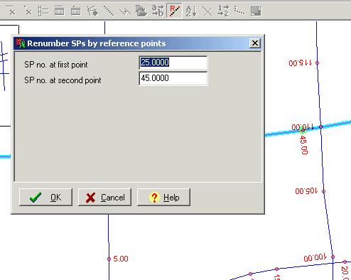
- Shotpoint Renumber

When merging different parts of the same seismic profile, it may be necessary to assign new shotpoint numbers to the location points. This option enables a range of shotpoints within a line to be renumbered to a new sequence. Enter the first and last shotpoint numbers for the range to be altered, followed by the corresponding endpoints for the new range.
- Waypoint

This option provides a convenient method for reducing the number of shotpoints in the .LOC file whilst maintaining a good approximation to the shapes of the profiles on the map. In the limiting case of a nearly straight profile, only the first and last shotpoint will be retained. The algorithm creates a new profile using the minimum number of shotpoints in such a way that the distance between the new and the old profiles is always less than the value specified for the maximum deviation parameter. In most cases, a maximum deviation of about 50 m will result in a considerable reduction in the number of shotpoints, whilst giving sufficient accuracy for profile intersection points to be within one trace accuracy
-
XY Shift and Rescale

XY Shift and Rescale has a number of uses:
- Add or subtract false Northings and Eastings
- Apply datum shifts in X or Y
- Change scale factor convert from metres to feet, or from feet to metres
In the X-Y rescale menu, four constants a, b, c and d are defined. New X and Y values are calculated for each location record, according to the formula
X = a + bX
Y = c + dY
The default values 0.0, 1.0, 0.0, 1.0 leave the X and Y values unchanged. To shift X and Y, enter the shifts in a and c, leaving b and d set to 1.0. To re-scale, leave a and c set to 0 and put the scale factor in b and d.
Note that the Latitudes and Longitudes are unchanged by this option.
- Auto-Split Profiles
- Projection
- Load Projection File
Browse for a projection configuration file to load
- Save Projection File
Save the current projection configuration file.
- Convert Projection
Edit the current projection conversion parameters and run the projection transformation. A new temporary LOC file will be created and displayed by LOCPREP, which can be saved using the File-Save As menu.
See Projection Conversions for details of supported projections and projection parameters. - Test Projection Coordinate
Test a coordinate conversion using the current projection transformation.
See Projection Conversions for details of the parameters and output.
- Load Projection File
- Check
- Geometry Test
See Location Geometry Test below
- Geometry Test
- Tools
Tools is a user configurable menu, which will appear if any external program tools have been installed. At startup, LOCPREP checks programs in the tools configuration list - if the programs are accessible, they will be displayed on the tools menu.
- Location File ASCII Dump - display the current file using LOCDUMP
4. Create New Profile from Intersections
If a profile is missing from the location file and from the map, you may be able to reconstruct its SP locations by looking for its intersections on the top strips of other profiles in the same area. You need the paper displays for these profiles, with the intersection information along the top strip (or raster images, or intersection listings). These lines must also be in the current .LOC file.
Make a list of the intersections, in the form
SP Linename SP-on-missing-Line
Select the Create New Profile
option and enter a name for the new profile. Now use the mouse to digitise the
known points of your new profile where it crosses other profiles.
Each time you select a point, a dialogue box will prompt you for the new shotpoint number, and you can
confirm or edit the shotpoint of the profile it crosses.
When you have completed digitising, select the Create New Profile
option again to un-toggle it and save your new line into the current temporary LOC file.
You can now edit the new profile, sort its shotpoints and interpolate the location points to a regular SP interval to create a regular profile which matches the other lines in the same survey.
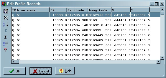
5. Edit Records for Current Profile
The Edit Records
option enables the fields in individual records to be altered manually.
Records for the current profile are displayed in a new window:
The buttons and popup menu provide the following functions:
- Edit Mode
 - toggle between row select mode and edit mode.
Row select mode allows you to select a range of records using the standard <SHIFT> key.
Edit mode allows to edit the record contents. - Delete Selected Records
 - delete the records which are currently selected
 - Order by Shotpoint
 - sort the records by ascending shotpoint value.
 - Edit Record ID
 - edit the Record ID for all records. For LOC files containing CD-VU cultural data or
well locations, the record identifier may need changing so that the data can be correctly
displayed. The default Record Identifier for seismic shotpoint locations is Q. Location data
imported from non-Lynx sources may have other record identifiers.
- edit the Record ID for all records. For LOC files containing CD-VU cultural data or
well locations, the record identifier may need changing so that the data can be correctly
displayed. The default Record Identifier for seismic shotpoint locations is Q. Location data
imported from non-Lynx sources may have other record identifiers. - First Record
 - skip to the first record
 - Last Record
 - skip to the last record
 - Remove duplicate shotpoints
 - remove duplicate
shotpoints.
- remove duplicate
shotpoints.
Sometimes, after merging, lines may contain one or more duplicate shotpoints. This button will remove them, but check first that essential data are not being removed in cases where the XY coordinates for the duplicated shotpoints may not be identical. - Help
 - show context help.
Click OK to save your changes to the current temporary LOC file, or Cancel to discard your changes
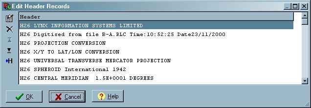
6. Edit File Header
The Edit File Header option allows the UKOOA header records
in the LOC file to be viewed and edited.
The buttons and popup menu provide the following functions:
- Edit Toggle - toggle between row select mode and edit mode.
Row select mode allows you to select a range of records using the standard <SHIFT> key.
Edit mode allows to edit the record contents. - Delete Selected Records - delete the records which are currently
selected
- Insert New Header Record
 - insert a new empty header record
 - First Record - skip to the first record
- Last Record - skip to the last record
- Help - show context help.
Header records must be prefixed by a 'H' character.
The UKOOA 84 and 91 standards list
mandatory and optional header records with the header codes to use. Lynx LOC files have no
mandatory headers, but none of the existing headers will be deleted, as long as all header records
precede all data records.
Click OK to save your changes to the current temporary LOC file, or Cancel to discard your changes
7. Join Profiles
The Join Profiles option enables two profiles
whose endpoints are close or overlapping to be joined as one profile. The shotpoint sequence on the new profile becomes
continuous and is inherited from the profile selected as the primary profile.
First, examine the profiles to be joined and decide the shotpoint on the primary profile at which the join is to take place. The location points in both profiles should be ordered so that the profiles both go in the same direction and the secondary profile "follows on" from the primary profile. Their shotpoint number sequences should also go in the same direction, either both increasing or both decreasing.
Select the primary and then the secondary profile, then click the Join Profiles
menu/toolbar button to enter Join Profiles mode.
As you move the mouse in the viewer window, the nearest shotpoint on the primary or
secondary profiles will be highlighted.
First, select the shotpoint on the primary profile at
which the join will take place.
Then select the first shotpoint on the secondary profile to
include in the joined profile:
After you have selected both shotpoints, a PRMEDIT dialogue box will be displayed for you to confirm the shotpoints selected. The dialogue also displays the calculated SP difference between the selected secondary shotpoint, and the projected shotpoint value from the primary profile. The SP Difference is the value subtracted from the shotpoints in the secondary profile to make them join smoothly with the primary profile. You can edit this difference if you believe that it requires adjustment.
Click OK to perform the join:
To exit from Join Profiles mode, and save the joined profile to the current temporary LOC
file, click the Join Profiles menu/toolbar button again to un-toggle
it.
8. Split Profile
Split a profile into two parts using the Split Profile option.
Select the profile to split and click the Split Profile
menu/toolbar button to enter Split Profile mode.
As you move the mouse in the viewer window, the nearest shotpoint on the current profile will be highlighted. The highlighted shotpoint will be where the second line-part starts. Click to select the shotpoint to split at.
In the displayed PRMEDIT dialogue, Select names for parts A and B of the profile, confirm the shotpoint at which to start part B, and specify the number of shotpoints overlap to use.
Click OK to perform the split.
To exit from Split Profile mode, and save the split profiles to the current temporary LOC
file, click the Split Profile menu/toolbar button again to un-toggle it.
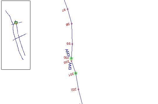
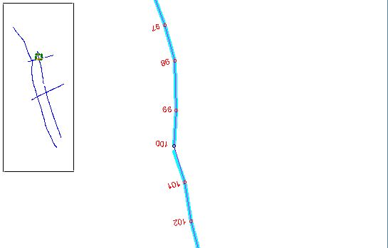
9. Renumber by SP and distance
Sometimes you may have incomplete information about the shotpoints along a line. For example, the line may have significant curvature or "bends" which have to be digitised, to define the track of the line, but the added nodes then lack shotpoint information.
This option will renumber all the shotpoints between two specified control points, using linear interpolation by distance. First, the total distance between the two control points is calculated, by summing the lengths of the segments in between. Then the shotpoint at each node is calculated by linear interpolation, according to the node's distance from the end points.
Before you start, make sure that shotpoint labels are turned on, so that you can see all
the shotpoint numbers on the line. Select Options|Edit Parameters|, or press
 on the main toolbar, then
page to the page "Line node (shotpoint) drawing" and set the node label properties.
on the main toolbar, then
page to the page "Line node (shotpoint) drawing" and set the node label properties.
Select the required profile and press
Set the first control point, by moving the cursor and clicking when the required point is highlighted. Set the second control point in a similar way. After the second point is selected, an edit window will appear in which you can enter the required shotpoint numbers for the chosen points. Note that shotpoints outside the chosen segment will be unaltered.
Press OK to apply the changes. You can now repeat the sequence - select another pair of
points - edit the numbers - OK, until all the shotpoints are as you want them. Press
again to exit.
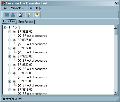
10. Location Geometry Test
The Location Geoemtry Test is accessed from the Check menu in LOCPREP. It can be used to check the internal integrity of the location data. This option will not perform a reconciliation of location data with seismic data - use Florence and Zebedee to do this.
Select the Parameters-Edit  menu to set the parameters for the error checking:
Report All Profile Statistics
YES - include all
profiles in output report
NO - exclude profiles where no errors found from output report
The following parameters specify the types of errors to include in the report:
Repeated Profile Names - YES/NO - check for profile names which are duplicated elsewhere in the LOC file
Bad XY Coordinates - YES/NO - check for missing/invalid XY coordinate for each record. This option must be set to YES for the Point-to-Point errors to be performed.
Bad LL Coordinates - YES/NO - check for missing/invalid latitude/longitude coordinate for each record.
Point-to-Point Distance - YES/NO - check that each location point is within a specified threshold of the average point-to-point distance between points
Distance Error Threshold - specify a percentage of the average distance between points calculated for each profile. Points which fall outside this percentage difference will be flagged as errors.
Point-to-Point Angle - YES/NO - check that each location point is within a specified threshold of the average direction of the profile.
Angle Threshold - specify an angle. Points which differ from the average direction by more than this angle will be flagged as errors/
SP Sequence Errors - YES/NO - check for repeated and non-sequential shotpoints
Max Errors per Profile - specify the maximum number of errors per profile. If more than this number of errors are found for a profile they will not be reported and the report skips to the next profile
Click the Run Geometry Test  menu to perform the test.
The output can be viewed in two formats:
- Click the Error Tree tab to display the errors in a hierarchical tree. You can double-click on an error to highlight it in the map in LOCPREP's main window.
- Click the Error Report tab to display a text report of the errors. This can be
printed or saved as a text file using the Print
 or Save As
 menus
menus
11. Metadata
Metadata means "data about data". In the case of UKOOA or LOC files, the metadata consist of supplemetary textual information that may be placed in the file header. The UKOOA 84 standard allows for general infomation in header records identied by the prefix "H26" and this is the convention adopted in LOCPREP. As the input file is edited in Locprep, information about each stage of the editing process is added to an internal list. On saving the file, the metadata are added to the output file header. This enables later users of the file to identify what changes have been made.
Changing the metadata prefix
The default prefix in Locprep is "H26M". This enables records added by Locprep to be distinguished
easily from general header records added by other applications, which may carry essential information.
This prefix is set in the LOCPREP.INI file [labels] section as "metadata prefix=H26M" so that it can be changed if necessary. However,
the first character of the prefix must always be "H" to enable applications to recognise the metadata as header records.
12. Error and Warning Messages
The following error and warning messages are produced by LOCPREP
Switch display coordinate system to display file?
The file you are attempting to open contains a different coordinate system to the current display
parameters. Standard "UKOOA"-type locations files usually contain both projected and unprojected
coordinates, so you can switch between the two coordinate systems within LOCPREP (see
General Parameters - Coordinate Display). However, some
locations files only contain a single coordinate system. This message warns you that the display
coordinate system is being changed in order to display the current file.