
Version: 5.3
Back to:
Lynx Exploration Archivist Trace Fix Up program TRACEFIX version 4 enables trace files to be speedily edited and repaired on a trace by trace basis. Existing users of Lynx's 3-S and Exploration Archivist software, will find that TRACEFIX not only retains all the familiar operations of its predecessor, TRCFIX, but adds new, more interactive facilities.
The main improvements in version 4, compared with TRCFIX version 3 are:
Features marked as not implemented are not operational in version 4, but will be implemented in upcoming versions. Note especially that horizon oriented operations for replacing, scaling or muting data are currently set up for single valued, single horizon segments only. Segment selection buttons on the horizon tool bar are therefore not activated.
A seismic file can be opened for editing in three ways:
- Select the File-Open menu option, and select the file in the open file dialogue
- Specify the file on the command line when starting TRACEFIX
- Drag the file from an explorer window, and drop it on TRACEFIX
- Drag the file from an explorer window, and drop it on the TRACEFIX icon in the Lynx Launcher.
TRACEFIX can conveniently be started by double clicking its icon in theLynx Launcher, or from a command line or script.
TRACEFIX can be run with a command line similar to the following:
TRACEFIX [TRACEFILE]
where:
TRACEFILE is an optional seismic data file. If no TRACEFILE is specified, you can select one from the dialogue box which appears when you click the File-Open menu or tool bar button.
When a seismic trace file is opened, it is copied to a temporary file, to which the modifications you make are applied. The trace file's TAX file is also opened for reading and writing auxiliary information. When you are satisfied with your changes, save the results in a new file, or overwrite the original. Use TRACEFIX's toolbars to apply operations to modify the displayed trace data.
Trace file headers can be modified from the Headers menu. Operations to be applied to traces are selected from the traces menu or the main toolbar.
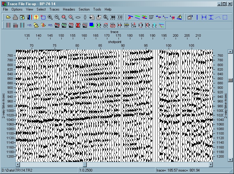
The main window contains tool bars and a rectangular display area which displays the contents of the currently open (temporary) trace file. Vertical scales located to the left and right of the display area show the corresponding time in milliseconds. Horizontal scale above the display area shows trace numbers in the file.
Most program functions can be invoked from TRACEFIX's four tool bars, which are grouped below the main menu, where most functions are also duplicated.
Bring up a Save dialog so that the current temporary file can be saved as a new
file. The trace file will be saved in the same format as the original input file.
For Lynx
Trace files the extension number will be incremented to create a new file each time you save by
default. If you wish to overwrite the current trace file instead of creating a new file, just
select the file to overwrite in the Save dialog, and click Yes when prompted to overwrite.
Saves the current state of the trace file's auxiliary file. This will normally have the same file name as the trace file, but with extension TAX.
Allows the existing temporary trace file to be saved as a different trace file type, eg SEG-Y files can be saved as Lynx trace files and vice versa.
The export traces dialog box contains the following options
Format
Select the output trace format. Select from:
- Lynx - Lynx format is Lynx's standard trace file format. Use this format if you wish to do further processing with Lynx's processing programs. Lynx format has a similar file structure to SEG-Y, but with ASCII CCard header, and trace samples either as IEEE floating point or scaled 2-byte integer. Trace headers carry floating point shotpoints, intersection labelling and other information which may be undefined in SEG-Y format
- Lynx(preserve) - this format can be used when the input file is SEG-Y format and you wish to preserve the SEG-Y header information on output, for example when handling pre-stack traces or data from stack tapes. Do not use this format for vectorised data.
- SEGY - use this format if you want to transfer data to other processing systems in SEG-Y format
- SEGY(Lynx) - SEG-Y Lynx Variant 3 a variation of SEG-Y in which the trace file name, first shotpoint, shotpoint increment and start time are stored in the SEG-Y binary header. Shotpoint and XY coordinate (if present) are stored in each trace header, in the header slots defined by the SEG-Y Revision-1 format. Start time is also stored in the trace header, in byte 233-234. This means that SEG-Y(Lynx) format files can be restored from a tape or disk file, for use with Lynx software, without the need to reset the shotpoint information. SEG-Y(Lynx) files can also be loaded into interpretation workstations using the TMin value to perform automatic static shifting for non-zero trace start times.
- Integer2 - each trace sample is stored as a 2-byte integer.
- Float4 - each sample is stored as a 4-byte floating point number. In Lynx format the samples will be in IEEE format. In SEG-Y, the samples will be stored as IBM 360/370 floating point format. Both these formats are more than adequate for preserving the full dynamic range of post-stack seismic data, without pre-scaling.
IMPORTANT NOTE. In Lynx integer-2 format, each trace is automatically scaled before it is written to file, in order to use the full dynamic range available in a 2 byte integer. The scale factors are stored in the trace headers, so that the traces can be rescaled to their original amplitude on reading back.
In SEG-Y format, trace samples are written to the file as 2-byte integer values, without prescaling. If you use SEG-Y 2-byte format you must pre-scale the traces before output to an RMS value of between 1000 and 2500, in order to ensure adequate dynamic range on the output SEG-Y data. The output file (Lynx or SEG-Y) can be scaled using the RMS balance option in the dialog box. When converting to SEG-Y fixed point (2 bytes / sample), use an RMS amplitude of about 2500, to avoid potential problems with sample value over- or underflow.
Remember that when changing file type, from SEG-Y to Lynx, or vice versa some header data may be lost, due to the differences in file structure. You are strongly advised to dum the trace file and check that header values are as expected.
If you change the file name (irrespective of its extension), any previously existing auxiliary TAX file will cease to apply to the renamed trace file. You may need to copy or rename the TAX file as well. This is NOT done automatically by TRACEFIX.
Changes you make here will be saved as your user-default display parameters for TRACEFIX, and used each time TRACEFIX is opened. You can discard all your changes and reset to the system default display parameters using the Options-Revert to Defaults menu option.
Lynx Trace files and SEG-Y files contain a 40-line text header at the start of the file, which can be edited to contain human-readable information. Each line (or C-Card) is 80 characters long. The header is displayed in a separate window.
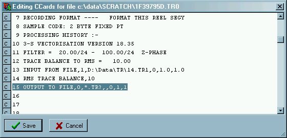
Lines will be automatically padded up to the maximum length of 80 characters.
Click Save to confirm your edits, or Cancel to discard them. Note that if you need to modify the CLIENT or LINE fields, on CCards 1 and 2, you should use the binary header editor to do so. This is because, in Lynx format trace and SEG-Y files, the CCard header is always updated so that it matches the values in the binary header when the file is re-written.
Binary file header editing in TRACEFIX V4 enables only limited modification of parameters relating to the current file's binary header. Some of the entries listed here are "pseudo parameters", that are not actually stored in the binary header, but are characteristic of it. These parameters are greyed out in the binary header display, because most of the time it is not necessary to change them. Other parameters are disabled, because doing so will corrupt the trace file and make it unreadable.
Client (string)
The Client name is obtained from the EBCDIC/ASCII text header of the trace file. (can change LYNX,SEG-Y)Profile Name (string)
The Profile Name is obtained from the EBCDIC/ASCII text header of the trace file. (can change LYNX,SEG-Y)Character format (ASCII/EBCDIC)
Character format of file header. For Lynx trace files, this will be ASCII. For standard SEG-Y this will be EBCDIC. Changing this parameter is not implementedTrace sample interval, msec (type single, limits 0.1 to 100.0)
If you change this, the Time of first sample will remain the same and the Time of last sample and Time length will change accordingly (can change LYNX,SEG-Y)Number of samples per trace (type short integer, limits 1 to 32000)
Changing this parameter is not implementedNumber of bytes per sample (type short integer, limits 1 to 4)
Changing this parameter is not implementedByte Order (type option, IBM, Intel )
Changing this parameter is not implementedSamples are Floating Point (type option, No, Yes )
Changing this parameter is not implementedFloating point format (type option, IEEE, IBM )
Changing this parameter is not implementedNumber of traces in file (type long integer, limits 1 to 32000)
This does not actually change the number of traces in the temporary file, but determines the number of traces written to the saved file. Traces after the last numbered trace will not be deleted, but will not be accessible unless the trace number is increased (can change LYNX)Time of First Sample, msec (type single, limits -10000.0 to 20000.0)
The start time of the traces (can change LYNX,SEG-Y)Time of Last Sample, msec (type single, limits -10000.0 to 20000.0)
The end time of the traces will change automatically to reflect changes made in Time of first sampleTime Length, msec (type single, limits -10000.0 to 20000.0)
Must be equal to Time of Last sample - Time of first sample, therefore cannot be changedTraces per CDP
(type short integer, limits 1 to 1000)
(can change LYNX)First CDP (type long integer, limits 1 to 32000)
(can change LYNX)Last CDP (type long integer, limits 1 to 1000)
(can change LYNX)CDP Increment (type short integer, limits 1 to 1000)
(can change LYNX)First Shotpoint (type single, limits -1.0E7 to 1.0E7)
This will not affect standard SEG-Y files, for which the First Shotpoint is not defined in the binary header. (can change LYNX)Shotpoint increment (type single, limits -1.0E7 to 1.0E7)
This will not affect standard SEG-Y files, for which the Shotpoint Increment is not defined in the binary header (can change LYNX)Last Shotpoint (type single, limits -1.0E7 to 1.0E7)
The last shotpoitn number will change automatically to reflect changes to the first shotpoint, shotpoint increment and number of traces.Trace Spacing, m (type single, limits 1.0 to 10000.0)
This will not affect standard SEG-Y files, for which the trace spacing is not defined in the binary header (can change LYNX)
The delete traces buttonallows one or more traces to be deleted from the trace file at a specified position. If you have specified a range of traces using the Selector toolbar, the trace numbers of the first and last traces will appear in the edit window on entry. Remember that trace numbers will change for traces after the deletion point. Deleting traces will also disrupt the sequence of values in the trace headers.
Delete at Trace no.
(type long integer, limits 1 to 10000)
The first trace to deleteNo. of Traces to delete
(type long integer, limits 1 to 10000)
The number of traces is equal to last trace - first trace +1.
This option deletes traces from the selected trace file using an input sequence, an ASCII file, or a calculated sequence as the source for a list of trace numbers to be deleted. As with Delete Traces, trace headers may not be correctly in sequence after this operation.
List Option
(type option File,Enter,Calculate)
Three options for genrating the list of traces to be deletedFile file, containing the trace numbers to be deleted, or enter the trace numbers below
File option requires a list of traces in an input ASCII file
(type filename)
The selected file should contain a single line in the form of a comma delimited list with the numbers of traces to be deleted in ascending order., e.g. 1,2,3,4,7,8,9,22,34,100,130,150The Enter option requires a list of traces to be deleted, on a single line.
The Calculate option is used when traces are to be deleted in a regular pattern, as when dead traces are to be deleted between blocks of good traces.
Enter comma delimited trace list
(type string )
The trace numbers to delete as a comma delimited list, e.g. 1,2,3,4,7,8,9,22,34,100,130,150The following parameters are used to generate a sequence of trace numbers which will delete traces in a regular sequence.
First trace to delete
(type long integer, limits 1 to 10000)
The trace number of the first trace in the file to be deletedno of traces to delete
(type long integer, limits 1 to 10000)
The number of adjacent traces to delete in each group of deleted tracesno. of blocks
(type long integer, limits 1 to 10000)
The number of groups of traces to delete. If the number entered is larger than the actual no. of blocks in the file, deletes will continue until the end of file is reached.block width traces
(type long integer, limits 1 to 10000)
The (output) no. of traces to keep in each block, between deleted groupsFor example, you may be dealing with data in which blocks of 24 traces are separated by two dead traces. The first block contains only 20 traces. In this case, enter
First trace to delete = 21
no of traces to delete = 2
no. of blocks =9999
block width traces = 24
Inserts zeroed traces at the specified insertion point. The trace headers for inserted traces will be zero.
Insert after Trace no
(type long integer, limits 1 to 10000)
Insert traces after this trace number.No of Traces to insert
(type long integer, limits 1 to 10000)
Number of traces to insert. On entry to the edit screen, this is set by the current selection as last trace - first trace + 1
Removes a specified number of traces from within a specified trace range. The trace numbers deleted will be equally spaced within the trace range. Remember that trace numbers will change for traces after the first trace deleted and that trace headers may need attention after this operation.
The number of traces to delete should not exceed 50% of the traces within the specified trace range (ie every other trace)
To make major changes to the number of traces in a file, or spatially reinterpolate the trace data, use the TRACEPREP RESPACE process.
Starting at Trace no.
(type long integer, limits 1 to 10000)
Specifiy the first trace of the range to be reducedEnding at Trace no.
(type long integer, limits 1 to 10000)
Specify the last trace of the range to be reducedReduce by
(type long integer, limits 1 to 10000)
The number of traces to remove from the specified range.
Merge traces from another trace file into the current (temporary) file. The file to be merged should have the same sample interval as the current file, but can have a different trace length and start time.
Merge after Trace no.
(type long integer, limits 1 to 10000)
The trace after which to merge in the new tracesMerge in traces from filename
(type filename)
The trace file from which data are to be mergedStarting at Trace
(type long integer, limits 1 to 10000)
The first trace to use from the merge fileEnding at Trace
(type long integer, limits 1 to 10000)
The last trace to use form the merge file.
Use this operation to split the current file at a particular trace or shotpoint, and create a new file containing the data to the right of the split point.
Split at SP/Trace - select from
- Trace - specify the split point as a trace number
- Shotpoint - specify the split point as a shotpoint
Split after SP/Trace no.
The "split point" is the trace or shotpoint in the current file after which the split will be made. Traces up to and including the split point will be preserved in the current file, and a new file will be created for the traces following the split point.Overlap traces
The new file will begin this number of traces to the left of the split point.New Line name for left part
You can specify a new line name for the current file (left part), after the split.Remove traces from left part - YES/NO
If YES, after the split, remove traces from the the current file, to the right of the split point.New Line name for right part
Specify a new line name for the new file (right part), after the split.File name for new (right) part
Specify the file name for the split part of the line, to the right of the split point. This file will be created when you click OK. If the file already exists, you will be prompted to overwrite it.
This operation enables a specified number of interpolated traces to be inserted uniformly into a range of traces. The inserted traces are equally spaced over the trace range. The sample values of the inserted traces are derived by summing in 50% from each trace on either side of it.
NB: If the number of traces to insert is relatively large (i.e. greater than 50%) compared with the trace range within which to insert the new traces, the simple form of interpolation used here may not be very satisfactory. For general spatial resampling, use TracePro RESPACE process, which uses spatial sinc function interpolation.
Insert after Trace no.
(type long integer, limits 1 to 10000)
Start inseting traces after this traceInsert before Trace no.
(type long integer, limits 1 to 10000)
The Last trace of the range in which traces are to be inserted.No. of Traces to insert
(type long integer, limits 1 to 10000)
For information on the muting options available see Muting Traces (below).
This operation overlays a specified trace range from a given file onto the current file.
Overlay onto Trace no.
(type long integer, limits 1 to 10000)
The fiirst trace onto which dat will be overlayed.Filename
The trace file, which is the source of the data to overlay on the current file. This must have the same sample interval as the current file, but can have a different number of samples per trace and/or start time. Traces will be aligned according to their start times before the output traces are generatedStarting at Trace
(type long integer, limits 1 to 10000)
Starting trace in the overlay fileEnding at Trace
(type long integer, limits 1 to 10000)
Ending trace in the overlay file. If the trace range overlaps the end of the current file, the current file's traces will be assumed to be zero in that range.Scale Factor
(type single, limits -1.0E6 to 1.0E6)
Scale factor by which to multiply the overlayed tracesTrace sample values are given by trace1 + (scale x trace2), where trace1 is a sample in the current file and trace2 is the corresponding sample from the overlay file.
Using a negative scale factor will have the effect of subtracting the overlay file from the input file.
This operation regenerates a specified part of a trace. The trace is first zeroed over the specified time range and then 50% of each of the traces on either side is summed in. This option is quicker to use than using separate zero and sum-in operations.
Trace Number
(type long integer, limits 1 to 10000)
The trace to regenerateStart Time msec
(type single, limits -1000.0 to 15000.0)
The start of the time range to be regenratedEnd Time msec
(type single, limits -1000.0 to 15000.0)
The end of the time range to be regenrated
This operation replaces part of a single trace with corresponding time samples from another trace, over a specified time range
Copy from Trace No.
(type long integer, limits 1 to 10000)
Source trace, from which to copy dataReplace at Trace No.
(type long integer, limits 1 to 10000)
Trace to be replacedStart Time msec
(type single, limits -1000.0 to 15000.0)
Start time for samples to be replacedEnd Time msec
(type single, limits -1000.0 to 15000.0)
End time for samples to be replaced
This operation replaces trace samples within a specified time window, centered on an event picked over the current file. Various kinds of interpolation and insertion can be used to replace the sample values in the selected window. Use this operation on hand picked events, such as residual timing lines, or "washed out" peaks or troughs, or interpretation marks, in order to replace bad sample values by interpolation from surrounding data, or overwrite with a pulse, wavelet or random noise.
Horizon data source - select from
- From polyline picks - use the current poly line as a source for the track of the time window across the display. The poly line buffer contains only a single horizon segment, so it cannot be used for discontinuous events.
- From current horizon - use the currently selected horizon as the source of the events for the sample replacement. Use of a horizon enables several discontinuous or overlapping segments to be replaced in one operation.
- All - the operation applies over all traces
- Selected - operation applies only over a selected trace range of traces. On entry to the edit window, the trace range is set according to the most recently used range or rectangle from the selection tool bar
From Trace Number
(type long integer, limits 1 to 10000)
Lower limit of the trace range over which data can be replacedTo Trace Number
(type long integer, limits 1 to 10000)
Upper limit of the trace range over which data can be replacedEdge blend traces
(type long integer, limits 0 to 100)
Taper the replacement in over this number of traces from the edge of the trace rangeTime window msec
(type single, limits -1000.0 to 15000.0)
The width, in time, of the time window. The maximum usable width will depend on the type of replacement (see below).
- cubic - samples are replaced be a cubic interpolation from the nearest trace samples above and below the time window. The time window should not be more than about one cycle wide, at the dominant frequency of the data.
- pulse - the centre sample in the replacement zone is replaced by a single pulse, of amplitude specified below
- random - the samples in the replacement zone are replaced by gaussian random pulses, having a zero mean and rms pulse amplitude specified below
- wavelet - the samples in the replacement zone are replaced by a wavelet, of amplitude and impulse response specified below. The zero time of the wavelet impulse response corresponds to the centre of the replacement zone
Pulse Amplitude
(type single, limits -100000 to 100000)
The amplitude for the pulse, wavelet or random sequence in the replacement zoneWavelet characteristics, for 2nd order Butterworth bandpass filter
Low cut, Hz
(type single, limits 0.1 to 10000.0)
Low cut -3dB amplitude frequency for the waveletHigh cut, Hz
(type single, limits 0.1 to 10000.0)
High cut -3dB amplitude frequency for the wavelet
A crude operation for rescaling a rectangular area. The start and end of the trace range are specified, using the Select toolbar rectangle. The scale factors at the start and end of the time range are entered manually. A factor > 1 increases the amplitude whilst < 1 decreases it. The scale factor is linearly interpolated over the time range.
From Trace Number
(type long integer, limits 1 to 10000)
Start trace at which to apply scalingTo Trace Number
(type long integer, limits 1 to 10000)
End trace at which to apply scalingStart Time msec
(type single, limits -1000.0 to 15000.0)
Time at which scale at start time is applied. Samples above this point are not rescaledEnd Time msec
(type single, limits -1000.0 to 15000.0)
Time at which scale at end time is applied. Samples below this time are not rescaledScale at start time
(type single, limits -1.0E6 to 1.0E6)
Start scale.Scale at end time
(type single, limits -1.0E6 to 1.0E6)
End scale.
This operation scales trace samples within a specified time window, centered on a picked event. Use it for boosting, or suppressing the amplitude along a selected horizon or event. The scale factor at the top and bottom edges of the window is unity and tapers linearly up to the scale specified at the centre of the window, i.e. at the picked event.
Source of event data - select from
- From polyline picks - use the current poly line as a source for the track of the time window across the display. The poly line buffer contains only a single horizon segment, so it cannot be used for discontinuous events.
- From current horizon - use the currently selected horizon as the source of the events for the scaling operation Use of a horizon enables several discontinuous or overlapping segments to be scaled in one operation. (horizon segments must be single valued)
Trace range limits the trace range over which operation can apply:
- All - the operation applies over all traces
- Selected - operation applies only over a selected trace range of traces. On entry to the edit window, the trace range is set according to the most recently used range or rectangle from the selection tool bar
From Trace Number
(type long integer, limits 1 to 10000)
Lower limit of the trace range over which data can be scaledTo Trace Number
(type long integer, limits 1 to 10000)
Upper limit of the trace range over which data can be scaledScale at window centre
(type single, limits -1.0E6 to 1.0E6)
The scale factor to apply at the centre of the time window, ie at the picked event.Window length msec
(type single, limits 2.0 to 6000.0)
The length of the time window centred over the picked eventEdge taper zone msec
(type single, limits 0.0 to 6000.0)
(not implemented) The Scale at Window centre is constant, outwards from the centre of the window, until this number of milliseconds from the window edges, at which point it tapers down to 1.0 at the window top and bottom edges. This parameter must be less than half the Window length, msec.Edge blend traces
(type long integer, limits 0 to 100)
(not implemented) A linear taper is applied this number of traces from the edge of the window, to bring the scale smoothly to 1.0 at the edge of the window. Prevents unseemly discontinuities at the left and right edges of the window. This parameter must be less than half the width of the window in traces.
This operation allows a specified range of traces to be shifted in time. The amount of shift can vary linearly across the shifted trace range, or can be taken from a picked horizon. Shifts of a non-integral number of samples are handled correctly using quadratic interpolation (for example, with a 4ms sample interval, a 10ms shift is 2.5 samples). The trace length is unaffected and the top or bottom of the shifted trace will be padded with zero samples, for a time equal to time shift. To avoid data loss at the beginning or end of the trace, pad the beginning or end of the traces with zeros before applying a shift.
- Linearly varying by trace Time shifts are entered for the first and last trace to be shifted. Time shifts in between are linearly interpolated.
- Shift using horizon times The time shifts for each trace are taken from the selected horizon. Outside the selected trace range, no shift is applied. (horizon segments must be single valued)
Starting at Trace
(type long integer, limits 1 to 10000)
The trace at which to begin time shiftingTime Shift msec
(type single, limits -10000.0 to 10000.0)
Time shift to apply at the start trace. A positive shift will move traces down, a negative shift will move traces upEnding at Trace
(type long integer, limits 1 to 10000)
The trace at which to end time shiftingTime Shift msec
(type single, limits -10000.0 to 10000.0)
Time shift to apply at the ending trace. A positive shift will move traces down, a negative shift will move traces upHorizon Name The name of the horizon containing the shifts to be applied
Add constant shift This constant is added to the horizon times before applying the sign (below).
Sign of shift This is applied to the (horizon shift + constant shift) before shifting the trace.
- Positive no action
- Negative the shifts are multiplied by -1.0 before applying to the traces.
This operation applies a stretch or compression factor to range of traces between given start and end times. A stretch factor greater than 1.0 will expand the trace whilst a factor less than 1.0 will compress it. If a different factor is given at the start trace than that at the end trace then the factor will change in a linear fashion over the trace range. Expansion will "lose" trace samples off the end of the expanded traces, whereas compression will result in zero sample values being "pulled in" to the ends of traces.
Starting at Trace
(type long integer, limits 1 to 10000)
Trace at which to start stretch operationStretch factor
(type single, limits 0.5 to 1.5)
Stretch factor to apply at the start traceEnding at Trace
(type long integer, limits 1 to 10000)
Trace at which to end stretch operationStretch factor
(type single, limits 0.5 to 1.5)
Stretch factor to apply at the ending trace.Start time
(type single, limits -1000.0 to 15000.0)
Start of time window over which the stretch is to be applied.End Time
(type single, limits -1000.0 to 15000.0)
End of the time window over which the stretch is to be applied. Below this level, traces will be pushed down (stretch) or pulled up (compress).
The sum operation allows a trace to be modified by summing in a proportion of the amplitude of another trace, over a specified time range. The source and "current" trace can be selected using the left and right edges, respectively, of the select rectangle tool.
Source from Trace
(type long integer, limits 1 to 10000)
The trace from which samples are to be copiedSum into current trace
(type long integer, limits 1 to 10000)
the trace into which samples are to be summedStart Time, msec
(type single, limits -1000.0 to 15000.0)
start time for the window over which samples are to be copiedEnd Time, msec
(type single, limits -1000.0 to 15000.0)
end time for window over which samples are to be copiedSource Scale factor
(type single, limits -1.0E6 to 1.0E6)
the scale factor to be applied to the source samples, before summing into the current trace.
The zero option enables a speciified rectangular region of the trace file to be zeroed. For more creative ways of zeroing traces, consider the various mute options available in TraceFix. You could also use the Scale time window along horizon operation with a zero scale factor.
From Trace Number
(type long integer, limits 1 to 10000)
Left side of window to be zeroedTo Trace Number
(type long integer, limits 1 to 10000)
Right side of window to be zeroedStart Time, msec
(type single, limits -1000.0 to 15000.0)
Top of window to be zeroedEnd Time, msec
(type single, limits -1000.0 to 15000.0)
Bottom of window to be zeroed
This button toggles the horizon toolbar, visible horizons and picked mutes on and off.
Muting is the process of zeroing out all or part of a seismic trace where no data are expected, or where there is extraneous noise. Most commonly, in marine data, a mute will be applied from the trace start time to the time of the first active sample on the trace, usually at the onset of the water bottom reflection. In this case, only the mute stop time need be specified, since the mute start time is automatically at the beginning of the trace. In this context, mute start means "the time of the first sample which is zeroed" and mute stop means "the time of the last sample which is zeroed". These correspond to mute time start and mute time end in the trace header and to the MUTESTART and MUTESTOP standard horizon names. Seismic trace file headers have slots called tmute1 and tmute2, corresponding to mute start and mute stop. These are normally both set to zero if no muting has been carried out.
In Lynx format trace files, the values stored in the trace header slots are in milliseconds (absolute). In SEG-Y revision 1, they are also defined as being in milliseconds, but there is no standard way of representing Tmin, the trace absolute start time. When a trace file is created, tmute1 and tmute2 are set to zero.
Rules for applying mutes.
Water bottom mutes can also be used for various purposes in Lynx's VelPrep and TracePrep seismic processing programs.
Select a standard mute horizon, in order to pick mute start or mute stop times. Mute horizons have standard names, normally MUTESTART and MUTESTOP (see startup configuration), corresponding to the times on a trace where the mute (region of zero trace samples) starts and ends.
If both MUTESTART and MUTESTOP horizons, are present, muting will be confined to regions where both are picked. If only MUTESTART is present, a mute will be applied from MUTESTART to the end of the data. If MUTESTOP only is present, the mute will be applied from the beginning of data, ie TMin in the file header, down to MUTESTOP. If you are picking a water bottom mute, you do not need to pick MUTESTART. See also Apply Mutes.
Select standard mute horizon - select from
- Mute start times - selects MUTESTART as the current horizon.
- Mute stop times - selects MUTESTOP as the current horizon, creates it if it doesn't already exist
The horizon tool bar is activated. If the selected mute horizon already exists, the first segment is copied into the polyline selector. Use the Polyline selector to edit the selected mute horizon.
If either MUTESTART or MUTESTOP does not exist, it will be created, as a horizon with one empty segment. The XY coordinate type defaults to shotpoint (up to V4.6 it defaulted to trace). To change this, edit the horizon properties for the selected horizon via the
horizon properties edit button on the Horizon tool bar, to give the required XY coordinate type.
The main seismic view window is now be horizon editing mode, allowing you to digitise a horizon which defines the mute.You can change the digitising mode, and apply your mute, using the context menu options available when you right-click in the viewer window:
- Append Points - default option
- Prepend Points
- Clear All Points
- Delete Point At Cursor
- Delete Points to End
- Insert at Cursor
- Move All Points
- Move Point At Cursor
- Save Selection Buffer - save changes to current polyline
- Save and Apply Mute - copies the current polyline to trace headers, and applies the mute. This is a quick-access option which applies the current mute to the seismic data using the most common options. Alternatively, you can select other options for applying the mutes using the Copy between Picked Polyline and Trace Headers or Apply Mutes options
Searches for a horizon (usually the mute stop time) by looking for the point on a trace at which the amplitude exceeds a percentage of the overall RMS amplitude for the whole trace. The auto picked times are stored in the polyline selector, so that they can be edited or copied into trace headers or horizons.
To use this option to pick a water bottom mute, proceed as follows
- All - the operation applies over all traces
- Selected - operation applies only over a selected trace range of traces. On entry to the edit window, the trace range is set according to the most recently used range or rectangle from the selection tool bar
Start Trace Number
(type long integer, limits 1 to 10000)
The starting trace at which to searchEnd Trace Number
(type long integer, limits 1 to 10000)
The ending trace at which to searchStart time msec
(type single, limits -1000.0 to 10000.0)
Search window start time, to limit the range over which the threshold search is carried outEnd time msec
(type single, limits -1000.0 to 10000.0)
Search window end timeThreshold % of RMS
(type single, limits -500.0 to 500.0)
The threshold as a percentage of the trace RMS. The pick is placed at the first sample in the search time window which exceeds the thresholdSetBack msec
(type single, limits 0.0 to 10000.0)
This amount is subtracted from the auto picked times
This operation transfers picked times in the current poly line into a selected trace header position.
The poly line buffer is visible as a thick line, representing a picked horizon, overlaying
the seismic data. It contains a set of trace vs time coordinates. By selecting a horizon segment,
you can transfer its data into the poly line buffer. Alternatively, to pick a poly line from
scratch, click the select poly line button
![]() and then define the poly
line by clicking the left cursor button at each node of the desired track over the seismic data.
Right click to view the polyline mode menu and save the polyline buffer to the current horizon
segment.
and then define the poly
line by clicking the left cursor button at each node of the desired track over the seismic data.
Right click to view the polyline mode menu and save the polyline buffer to the current horizon
segment.
- Poyline to trace header - copies from the polyline buffer to the trace header position selected below.
- Trace header to polyline- copies from the trace header position selected below to the polyline buffer.
- All - copy to trace headers over entire trace range spanned by currently picked polyline
- Selected - copy over range of traces selected below, where poly line is also picked
Start trace
(type long integer, limits 1 to 10000)
The first trace of the selected range
End Trace
(type long integer, limits 1 to 10000)
The last trace of the selected rangeTrace header location
The trace header position (Lynx or SEGY format) to copy to, or from the polyline buffer. (Select from one of the following trace header positions)
- Lag time A
- Lag time B
- Delay recording time
- Mute time, start
- Mute time, end
Taper, msec
If non-zero, a taper will be applied into the muted zone, which will reduce the scale factor to zero over the number of milliseconds entered. This will make the mute appear less abrupt and more natural.Write to headers
(type option Yes,No)
Yes - write the mute time, in milliseconds, for each trace into its trace header. MUTESTART will be written into Tmute1 and MUTESTOP into TMute2. The mutes can then be re-applied later, in TRACEPREP, without reference to the trace auxiliary file.
No - do not write into the trace headers.Trim to edges(type option Yes,No)
Yes - extend the mutes out to the first and last trace in the section. The mutes will be extended horizontally to the first and last traces, using the mute times at the nearest picked points.
No - apply mutes exactly as picked - do not extend to first and last traces.
Clear (set to zero) mutes stored in the trace header Mute time, start and Mute time, end positions. This operation doesn't affect the trace samples, it only changes the trace headers.
Trace range
(type option All, Selected)
The range over which to clear the mutes.Start trace
(type long integer, limits 1 to 10000)
First trace form which to clear mutes
End Trace
(type long integer, limits 1 to 10000)
Last trace from which to clear mutes
Apply mutes to the trace data. The mute information must previously exist as mute horizons, as a picked poly line, or in the trace headers
Use data from - determine the source of the mutes:
- Polyline picks - the traces are muted, using the current poly line buffer. This should be made visible first, by clicking the Select PolyLine button
, before you select the Apply Mutes operation.
- Trace headers - the traces are muted, using data from the trace header mute start and stop times. If these are both zero, no mute will be applied.
- Mute horizons - the traces are muted using data from the standard horizons MUTESTART and MUTESTOP. Mutes will only be applied over trace ranges where both these horizons are defined. If either horizon is absent at any given trace, no mute will be applied to that trace (see Select Mute Horizon)
- All - the operation applies over all traces
- Selected - operation applies only over a selected trace range of traces. On entry to the edit window, the trace range is set according to the most recently used range or rectangle from the selection tool bar.
Start trace
(type long integer, limits 1 to 10000)
First trace at which to apply mutes. If using mute horizons, or polyline options, these must be defined at any given trace within the selected trace range, in order for mutes to be appliedEnd Trace
(type long integer, limits 1 to 10000)
End trace at which to apply mutesTaper msec
(type single, limits 0.0 to 1000.0)
The trace will taper down to zero within the muted zone, over this time range. This will give the data a smoother, more natural appearance than a sharp cutoff with no taper.Write to headers
Yes - write the mute time, in milliseconds, for each trace into its trace header. MUTESTART will be written into Tmute1 and MUTESTOP into TMute2. The mutes can then be re-applied later, in TRACEPREP, without reference to the trace auxiliary file.
No - do not write into the trace headers.Trim to edges
Yes - extend the mutes out to the first and last trace in the section. The mutes will be extended horizontally to the first and last traces, using the mute times at the nearest picked points.
No - apply mutes exactly as picked - do not extend to first and last traces.
All Lynx Exploration Archivist application programs have a corresponding INI file in the Lynx system directory. The [startup] section contains program constants which can be edited manually, or through the LEAConfig application.
width=640
Sets the initial width in pixels of the TRACEFIX main window.height=480
Sets the initial height in pixels of the TRACEFIX main window.The default window height and width will only be used the first time TRACEFIX runs. After its first run, TRACEFIX reads its window size and position from values stored in your USER.INI configuration file.
mute1 name=MUTESTART
The standard name for the horizon used for storing mute start times. If you change this name in TRACEFIX, you must change it to the same name in all other programs using the horizon data for muting.mute1 descrp=mute start time
The description of the mute start time horizonmute2 name=MUTESTOP
The standard name for the horizon used for storing mute stop times.Shotpoint/trace split point out of range bad sp split
time
The description of the mute stop time horizon
External tools are executable programs which appear on the Tools main menu item. These are listed in the [tools] section of TRACEFIX.INI in the form
exename=filetype,description
where
exename (with or without extension .exe, .com, .bat etc.) is an executable
file. If the extension is omitted, .exe is assumed.
filetype is an optional keyword which
causes the selected tool to be recognised as a seismic tool and to open the current temporary file
displayed by TRACEFIX. This keyword defaults to the value specified by the seisfile
keyword in the [labels] section of TRACEFIX.INI
description is a description of
the program, as it will actually appear under the Tools menu eg
[tools]
SeisView=seisfile,Lynx Seismic Viewer
TraceDmp=seisfile,Lynx Trace File Dump
NotePad=Text editor
Data relating to the current trace file's auxiliary TAX file have changed. Decide whether you wish to save the changes.
Shotpoint/Trace split point out of range
The chosen shotpoint or trace is not in the range of traces, or shotpoints, existing in the file.
The trace file specified for a merge or overlay operation cannot be found. Retry the operation using the name of an existing trace file.
The trace file specified for a merge or overlay operation cannot be opened. It may be opened "read/write" by another user, or you have not got permission to access the file
A time range was specified with start time > end time
A trace range was specified with first trace number > last trace number
An attempt was made to apply based horizon mutes, when no mute horizons were specified
An attempt was made to save the selected polyline, but no horizon is defined in which to save it. If picking mutes, you need to select a mute horizon (usually the mute stop time) before saving the picks.
In a merge operation, the file being merged had a different number of samples per trace from the current file. If the number of samples, after allowing for relative start times, is greater than the current file, the additional samples will be ignore. If shorter, the data will be zero padded.
An attempt was made to overlay or merge a trace file with a diferent sampling interval from the current file
A prompt to confirm that an exisiting trace file can be overwritten
A prompt to confirm that TAX file data are to be saved to an existing file, overwriting its existing data.
In a Less Traces operation, the number of traces to remove was greater than the number of traces in the selected range
On closing TRACEFIX, this prompt allows you to decide whether to save the modifications made to the input trace data.
Confirmation message that mutes should be cleared
See also:
[SEISVIEW - Seismic Viewer]
[TRACEDMP - Seismic Trace File Dump]
[Viewer
Common Functionality]
[PRMEDIT - Parameter Editor]
[Main Index]